
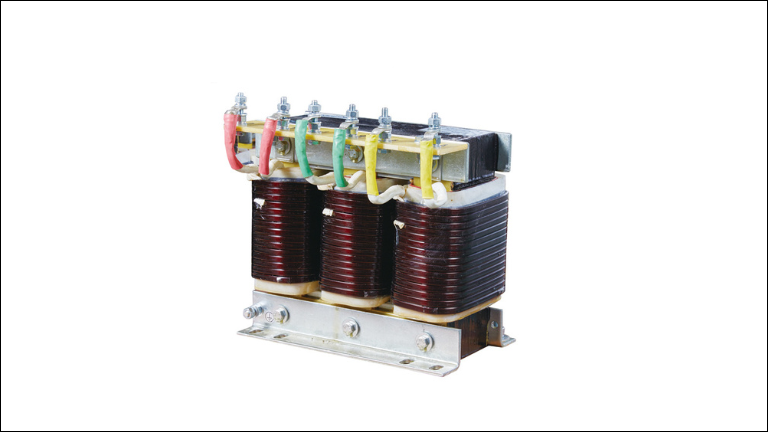
A 3-phase line reactor is an electrical component used in applications involving Variable Frequency Drivers (VFD) to protect and stabilize three-phase power systems.
Testing a 3-phase line reactor involves steps like
1. Inspect Any Visual Damage
2. Test Resistance for Proper Winding Integrity
3. Inductance Measurement
4. Insulation Resistance
5. Impedance Testing
6. Functional Testing Under Load Conditions
Step 1. Visual Damage Inspection
Visually inspect the line reactor for any physical damage, such as cracks, dents, or loose connections. Ensure that all terminals and connections are secure and free from debris.
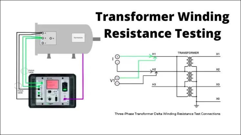
Step 2. Testing Resistance for Proper Winding Integrity
The purpose of testing reactor winding resistance is to conduct pre-commissioning checks to detect abnormalities such as –
1. Loose connections
2. Broken strands
3. High contact resistance in tap changers
Considering low resistance levels involved, Transformer ohm meters are optimum in measuring resistance accurately. It’s important to apply an adequate current to saturate the core swiftly, reducing measurement time while ensuring accuracy.
Temperature precision is paramount during testing. It’s necessary to be careful when monitoring to minimize self-inductive effects and ensure stabilized currents prior to measurement.
The sequence of tests is strategic, with winding resistance typically conducted last to prevent potential interference with subsequent assessments like magnetizing current and magnetic balance tests. This precaution ensures reliable and accurate evaluation of the reactor’s performance.
Step 3. Measure Inductance
XL = 2πfL
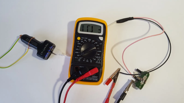
The inductance of each phase (Lk) is determined using the formula Lk=Vk/(2πfIk) where Vk is the voltage in volts, Ik is the current in amps, and k represents the phase number (1, 2, or 3).
For testing, three voltage and three current meters are required, and typically,
inductance is measured at a single current value. The difference between the outer and middle coils (about 4 to 9%) is usually disregarded.
Step 4. Check Insulation Resistance
To check the insulation resistance of a line reactor, the CT secondary and ground conventional test instrument is typically used. First, the neutral ground must be disconnected, and the CT should be isolated from its burden.
The neutral can be used to test all three phases simultaneously. Each core is tested individually by grounding the other cores temporarily to ground using a 500 V megger for 1 minute.
The insulation resistance (IR) value obtained is compared with known values for similar devices or circuits. A generally accepted minimum IR value is 1 MΩ. If the readings are lower than expected, it could indicate moisture presence. In such cases, drying out the equipment and retesting should be considered before dismantling.
Precaution – note that if relays are left connected to the CT during the test, it’s
important to consult the relay manufacturer before using test values above 500 V. it’s because some solid-state relay designs have surge-suppression capacitors connected from input terminals to ground, which could be damaged by higher voltages.
Step 5. Impedance Testing
Impedance testing for a 3 phase line reactor involves assessing how effectively it resists changes in alternating current (AC) flow. By measuring its impedance, which is essentially its resistance to these changes, we can understand how well it’s performing its role in managing electrical power.
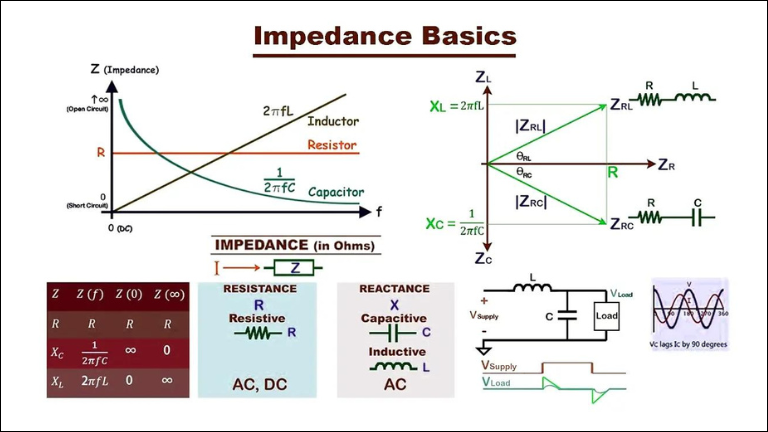
During the test, the line reactor is connected to an adjustable 3-phase AC power supply. Each coil is carefully adjusted to ensure electricity flowing through it falls within the appropriate range. Voltage measurements are then taken across each coil to evaluate its impedance.
These voltage measurements, along with the frequency and current settings, are used to calculate the impedance of the line reactor. By comparing this calculated impedance with known standards or manufacturer specifications, we can determine if the reactor is operating within acceptable limits.
Precaution – Before testing the impedance of a 3-phase line reactor, ensure safety measures are in place – including but not limited wearing proper gear and isolating the electrical system. Only trained & experienced personnel should conduct the test. These precautions ensure safe and effective impedance testing.
Step 6. Functional Testing Under Load Conditions
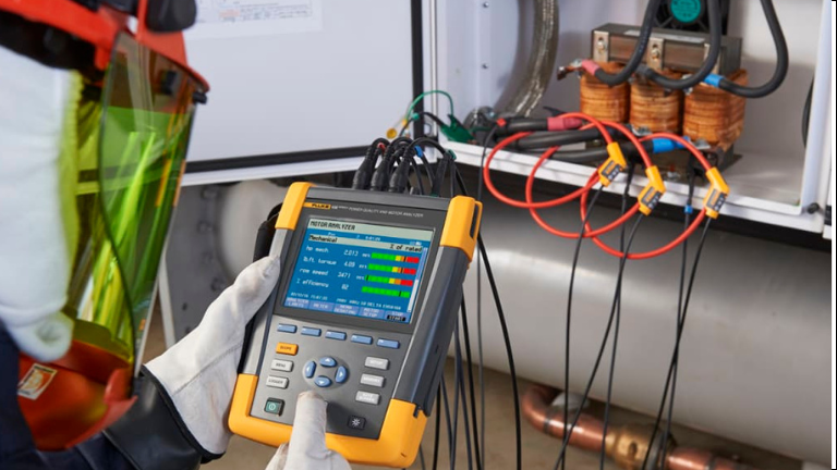
Functional testing under load conditions for a 3-phase line reactor involves evaluating its performance while actively connected to electrical equipment, like motors. During this assessment, the line reactor is integrated into the electrical system, allowing current to flow through it as in typical operations.
The focus is on assessing how effectively the line reactor manages electrical power, ensuring stable voltage and current levels. This entails measuring parameters such as voltage, current, and power factor both upstream and downstream of the reactor to gauge its efficiency in regulating power flow.
Precautions
Here are some common safety measures that you must adhere to before testing a 3 phase line reactor functional testing under load conditions
Safety: Follow safety protocols, wear proper gear.
Qualified Personnel: Only trained individuals should conduct tests.
Isolation: Ensure electrical system isolation before work.
Calibration: Check equipment for accuracy.
Load: Don’t overload the system.
Conclusion
Testing a 3-phase line reactor is important to ensure if it is working safely and effectively in an electrical system. By following proper procedures, we can accurately measure its performance. This testing helps us identify any issues, protect against potential hazards, and ensure the reactor operates reliably.
Overall, conducting these tests ensure the smooth functioning of electrical systems and promotes safety for all involved.