A linear actuator is a device that creates motion in a straight line. It helps push and pull objects along a straight path. Calculating a linear actuator position is crucial for it to work efficiently. To calculate linear actuator position, you can use various methods depending on the level of precision required and the tools available.
What is a Linear Actuator?
A linear actuator is a device that converts energy, typically from an electric motor into straight-line motion. Unlike a regular motor that spins in circles, a linear actuator moves things back and forth along a straight path. This movement is essential in many machines and devices where precise control and positioning are required.
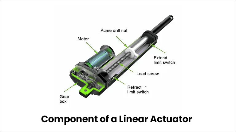
How a Linear Actuator is Made (Components)

Motor: Powers the actuator.
Gearbox: Adjusts the motor’s output for the desired speed and torque.
Lead Screw: Converts rotational motion to linear motion.
Drive Nut: Moves along the lead screw to create movement.
Extend Limit Switch: Stops the actuator at its fully extended position.
Retract Limit Switch: Stops the actuator at its fully retracted position.
Acme Drill Nut: Translates the rotation of the lead screw into linear motion.
Types of a Linear Actuator
There are several types of linear actuators used in various industries, while these are the most common types:
- Electric Linear Actuators
- Hydraulic Linear Actuators
- Pneumatic Linear Actuators
Electric Linear Actuators
These use an electric motor and are popular for their precision and control. They are commonly used in home automation and industrial machinery.
Hydraulic Linear Actuators
These use pressurized fluid to create motion and are very powerful, often used in heavy machinery like construction equipment.
Pneumatic Linear Actuators
These use compressed air and are fast and efficient, typically found in factory automation and lightweight machinery.
Simply Ways to Calculate Linear Actuator Position (Step-by-Step Guide)
Here are the steps for calculating the position of a linear actuator using various methods.
- Manual Measurement
- Using Built-in Sensors
- Using a Linear Actuator Calculator
- Trigonometric Calculation
1. Manual Measurement
Move the actuator to the desired position using the control system or manually if possible. Use a measuring tape or a ruler to measure the distance from the base of the actuator to the end of the rod. Note down the measured length. This is the current position of the actuator.
If you have a linear actuator that extends to a maximum of 20 inches and you measure the distance from the base to the end of the rod as 10 inches, the actuator is halfway extended.
2. Using Built-in Sensors

Identify the Type of Built-in Sensor (e.g. Potentiometer/Hall Effect Sensor/Encoder). Ensure the Sensor is properly connected to the Control System that Reads the Sensor Output. If necessary, calibrate the sensor by setting the fully extended and retracted positions. Use the control system’s interface to read the position data provided by the sensor.
An actuator with a built-in potentiometer provides an output of a voltage between 0V (fully retracted) and 5V (fully extended). If the control system reads a voltage of 2.5V, you know the actuator is halfway extended.
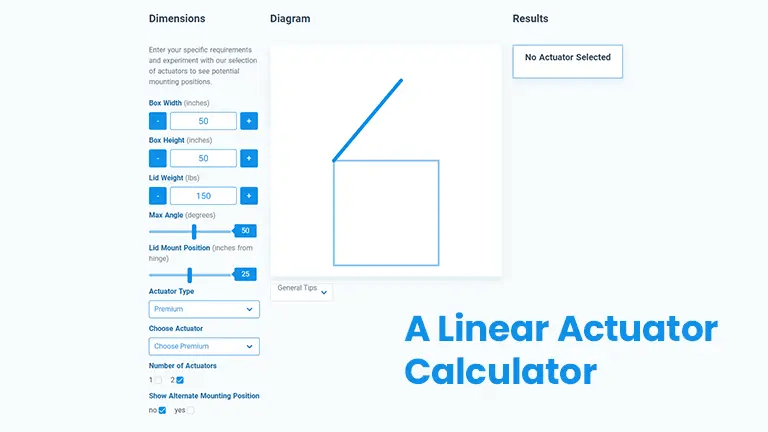
3. Using a Linear Actuator Calculator

Collect the necessary specifications of your actuator, such as stroke length, motor speed, and gear ratio. Use an online linear actuator calculator or software. Input the specifications into the calculator. The calculator will use the input data to determine the actuator’s position based on the current input (e.g., time, motor rotations).
For an actuator with a stroke length of 10 inches, a motor speed of 2 inches per second, and an operation time of 3 seconds, the position can be calculated as:
Position = Motor Speed × Time= 2in/sec × 3 sec = 6 inches
So, the Actuator is extended to 6 inches.
4. Trigonometric Calculation
Determine the angles and lengths involved in the system. Apply relevant trigonometric formulas (e.g., sine, cosine) to calculate the position based on the actuator’s movement. Use the calculated angles and lengths to determine the exact position of the actuator in the system.
Consider an actuator that controls the angle of a robotic arm. If the actuator moves the arm from a 30° angle to a 60° angle, and the length of the arm (hypotenuse) is 15 inches, you can use the cosine rule to calculate the change in position:
Position = Arm Length × (cos(30°) − cos(60°))
Position=15 inches×(3/2−1/2)≈15 inches×0.366=5.49 inches
So, the actuator’s position change is approximately 5.49 inches.
Factors to Consider Before Calculating The Position of a Linear Actuator
Accurately calculating the position of a linear actuator is essential for many applications. Before diving into the calculation, several factors and considerations need to be addressed to ensure precision and reliability. Here’s a few key points to keep in mind –
- Actuator Type
- Sensors Used
- Environmental Factors
- Load Characteristics
- Power Stability
- System Integration
- Accurate Position Measurement
- Proper Calibration
- Maintenance
- Cost Consideration
Before calculating the position of a linear actuator, it’s crucial to consider these key points for the accurate and precise actuator position calculation for your application.
Conclusion
The choice of method for calculating the position of a linear actuator will depend on your specific application needs, the precision required, and the complexity of the system. Manual methods are suitable for simple, low-cost applications, while built-in sensors and trigonometric calculations are better for high-precision and automated systems. Using a linear actuator calculator can be a quick and efficient way to plan.
By understanding these methods and their applications, you can effectively determine and control the position of linear actuators, enhancing the performance and reliability of your systems.

